Custom THT inductors: coils and chokes – Production of dedicated through-hole inductors for electronics and industry
Despite the dynamic development of (partly competitive) SMD technology, traditional through-hole chokes (THT) remain a key component of modern electronics, power electronics, and the automotive industry. In applications requiring high reliability, connection strength, and mechanical durability, dedicated through-hole THT chokes offer capabilities often unavailable with alternative components!

What are THT inductors?
THT chokes are inductive components mounted through PCB holes. Alternatively, or rather colloquially, this term sometimes refers to all chokes mounted on wires and cables, often using a through-hole method in the automotive industry.
The key feature of THT chokes is their wire leads, which are directly connected to the electrical supply. Thanks to their large connection surface area and robust mechanical mounting, they are ideal for high-power systems, such as converters, inverters, automotive solutions and systems, industrial power supplies, PFC systems, medical devices, renewable energy systems, EV chargers, and military and railway equipment.
Modern THT inductors are designed for high mechanical and thermal resistance, as well as high current handling – all while maintaining EMC compliance and minimizing losses.
Below are the approximate ranges of electrical and mechanical parameters:
| PARAMETER | THT – THROUGH-HOLE TECHNOLOGY CHOKES | |
| Wire type | Solderable and non-solderable: CuL 155 – 200, Gr.1 – 2 (typically) Selfbonding: FSP 18, STP 18, PSP 15 and etc. | |
| CuAg silver-plated wires for HF applications | ||
| Other types of wires are available on request. | ||
| Wire diameter | Min | 0.1 mm |
| Max | 2.10 mm | |
| Other wire diameters are available on request. | ||
| Winding direction | Left, Right | |
| Number of winding layers | Typ. | 1 |
| More | TBD | |
Coil shape | Usually cylindrical, spool or bar | |
| Possibility of placing a UV glue point for automatic assembly (Pick & Place machines). | ||
| Unusual, non-typical shapes or requirements – Possibility of individual arrangement upon request. | ||
Types of cores used | Ferrite Cores, Powder Cores, Metal Composite | |
| Typical saturation current ranges (Isat) |
| |
| Typical DC resistance (DCR) |
| |
| Typical operating frequency | Depends on the application and the choice of materials (especially the hysteresis of the ferrite core)
| |
| Leads | Typically – insulation removed As requested – tinned | |
| Other versions are available upon request. | ||
| Location and shape of leads | Typically – axial or radial. Length to be determined. | |
| Depending on the core shape – pinout according to the core and customer requirements. | ||
Tinning / Soldering | Pb-Free | |
| Pb (on request) | ||
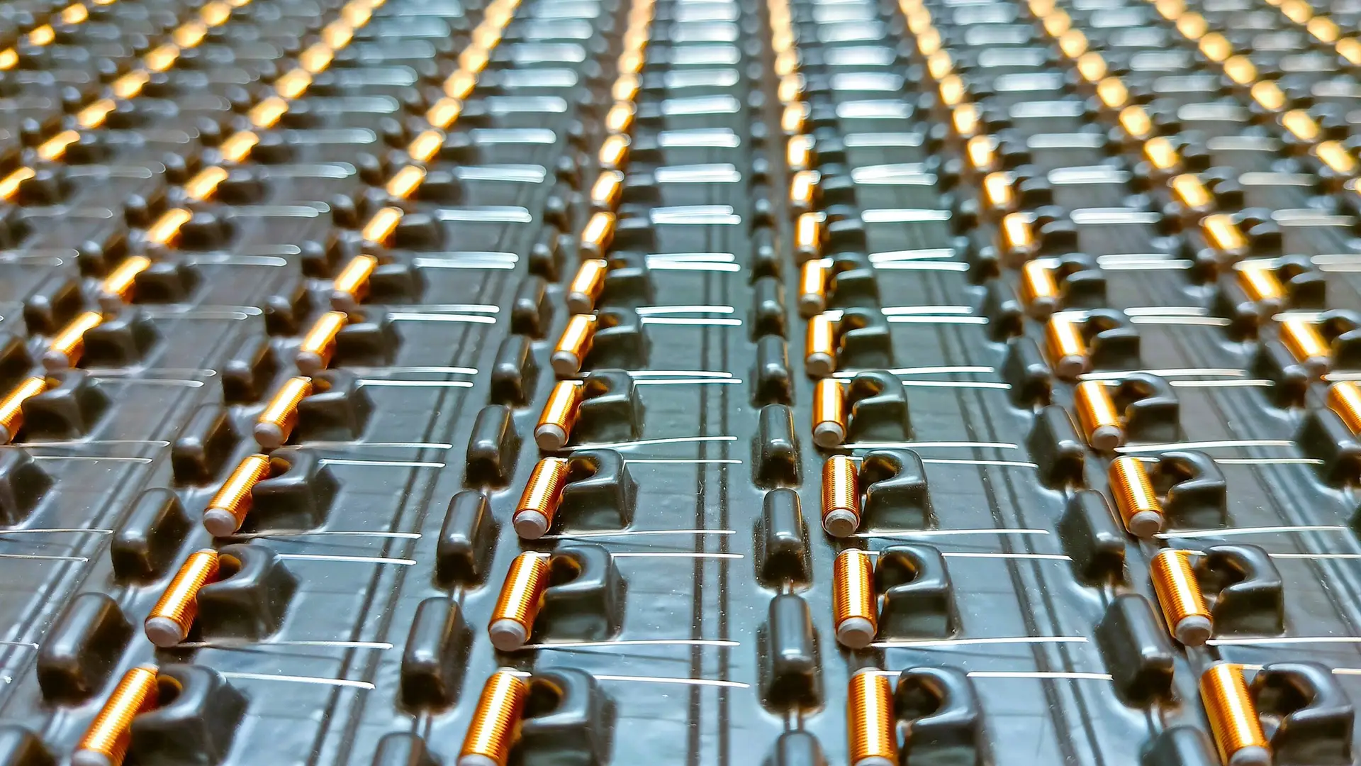
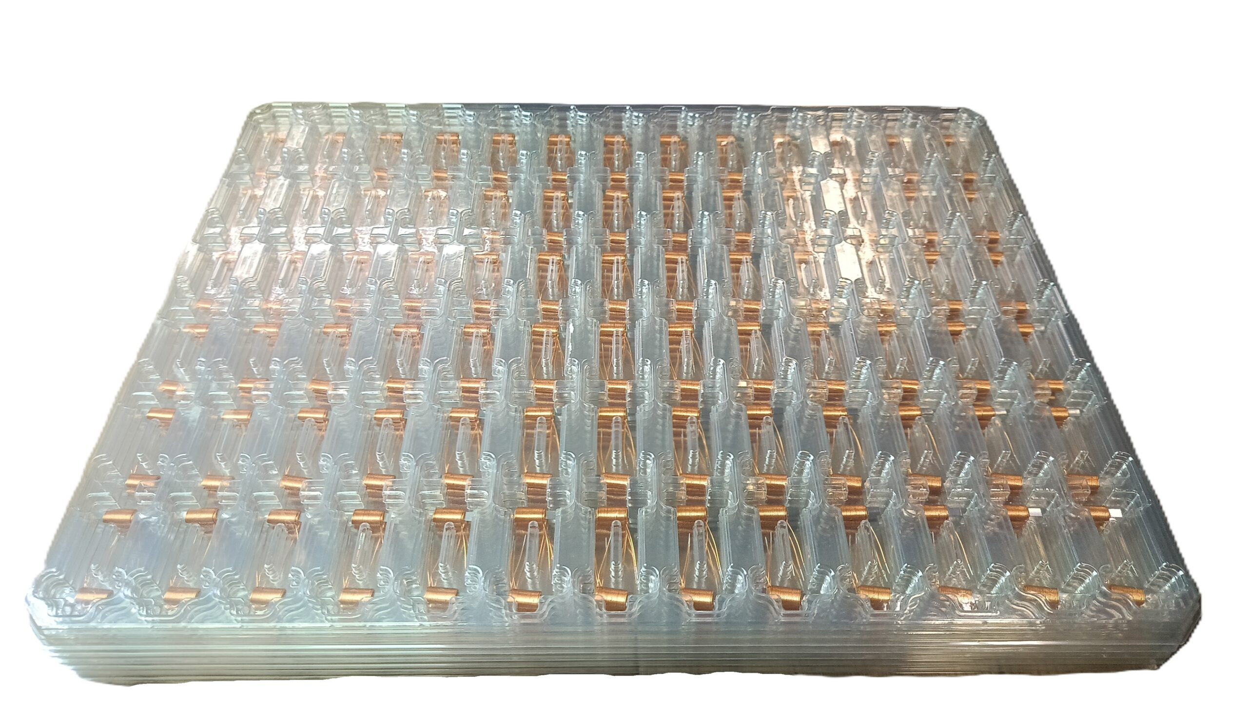
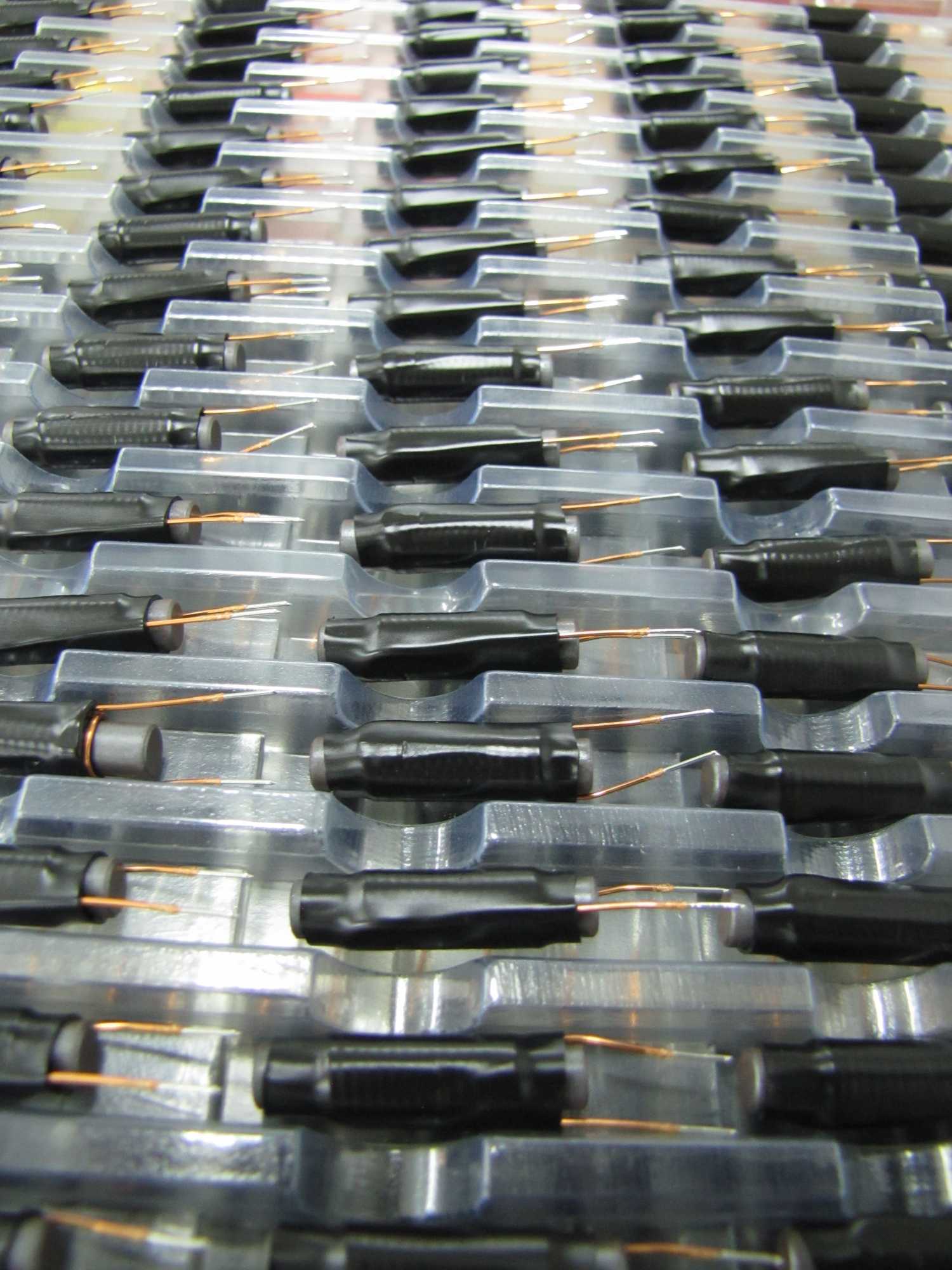
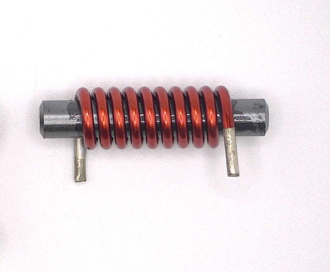
Gallery: