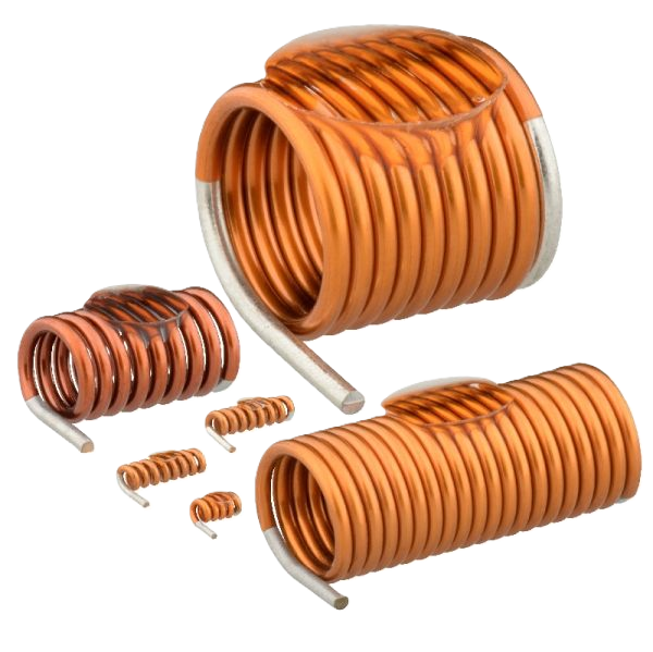
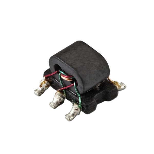
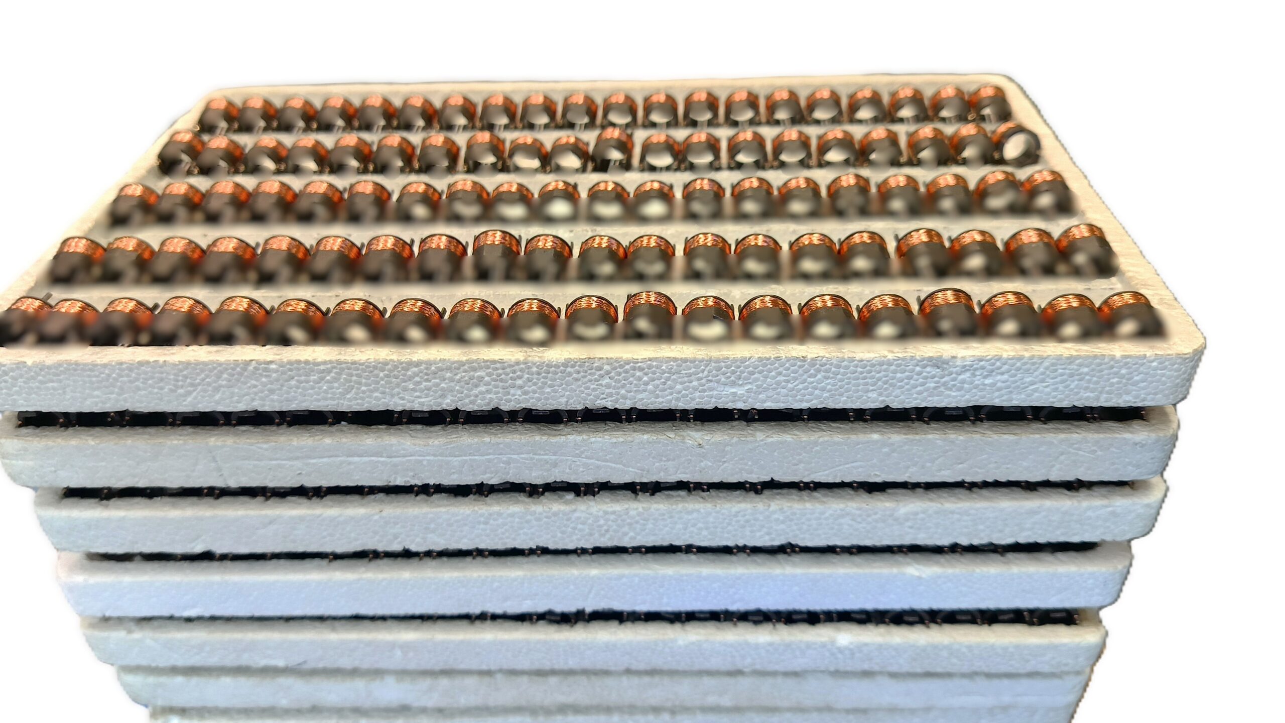
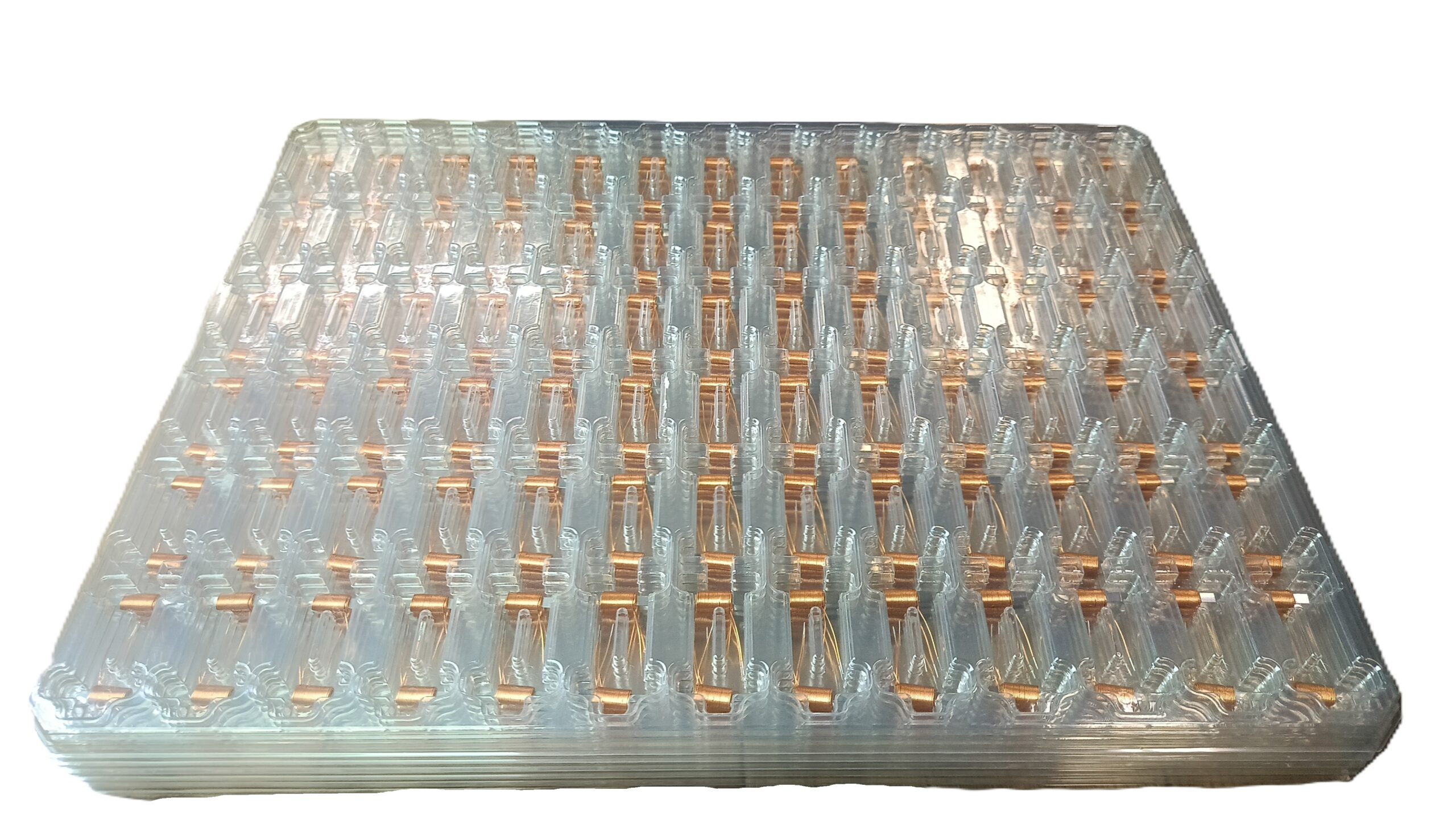
RF Signal Inductors - production of dedicated RF (high frequency) coils for telecommunications, IoT, and RF electronics
The development of 5G, IoT, Wi-Fi 6/7, automotive radars, and wireless communication systems is driving an increasing demand for RF signal coils and high-frequency inductors. Dedicated RF inductors are components of radio frequency (RF) circuits, signal filters, impedance matching circuits, and microwave solutions.
Producing custom RF inductors enables optimization of:
- Q factor,
- SRF resonant frequency,
- S parameters,
- impedance,
- insertion loss,
- temperature stability.
Additionally, it enables miniaturization of PCBs and RF circuits and – depending on the design – improves EMC/EMI compatibility parameters.
Modern RF signal inductors are manufactured for GHz applications. They are typically characterized by very low losses and high parameter stability in high-frequency environments.
What are RF signal inductors?
RF signal coils, chokes and inductors for specialized telecommunications and industrial applications are designed for high-frequency applications. They are most commonly found in radio frequency (RF) circuits, microwave electronics, wireless communication systems, signal filtering, measurement systems, amplifiers, and PLL circuits.
Unlike traditional power inductors, RF inductors are designed primarily for Q factor, high SRF, minimal AC losses, low parasitic capacitance, and performance characteristics, primarily at a very specific, specified frequency (often in the GHz range).
Signal inductors - Most important technical parameters
The precise electrical parameters of signal chokes are crucial for impedance matching, filter tuning, resonance operation, and RF signal stability. The precise inductance value is primarily responsible for this. Equally important is the choke’s quality factor (Q), which ensures lower losses, higher RF efficiency, better filter selectivity, and higher signal quality.
Below are the approximate ranges of electrical and mechanical parameters:
| PARAMETR | RF SIGNAL INDUCTORS | |
| Wire type | Solderable and non-solderable: CuL 155 – 200, Gr.1 – 2 (typically) Selfbonding: FSP 18, STP 18, PSP 15 and etc. | |
| CuAg silver-plated wires for HF applications | ||
| Other types of wires are available on request. | ||
| Wire diameter | Min | 0.04 mm |
| Max | 2.10 mm | |
| Other wire diameters are available on request. | ||
| Winding direction | Left, Right | |
| Number of winding layers | Min | 1 |
| Max | TBD | |
Coil shape | Depends on the shape of the ferrite core. Cylindrical, spool, bar, and others. | |
| Possibility of placing a UV glue point for automatic assembly (Pick & Place machines). | ||
| Unusual, non-typical shapes or requirements – Possibility of individual arrangement upon request. | ||
Types of cores used | Ferrite Cores, Powder Cores, Metal Composite | |
| Typical saturation current ranges (Isat) |
| |
| Typical DC resistance (DCR) |
| |
| Typical operating frequency | Depends on the application and the choice of materials (especially the hysteresis of the ferrite core)
| |
| Leads | Typically – soldered to the core | |
| Compression-welded | ||
| Metallized with silver wire for reinforcement | ||
| Other designs available upon request. | ||
| Location and shape of leads | Typically – wrapped around specific points on the core. | |
| Dependent on the core shape – pinout according to the core and customer requirements. | ||
Soldering | Pb Free | |
| Pb (on request) | ||
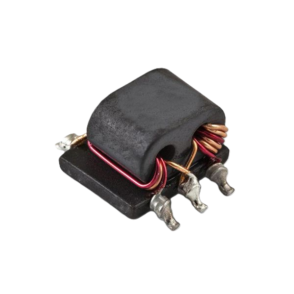
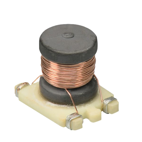
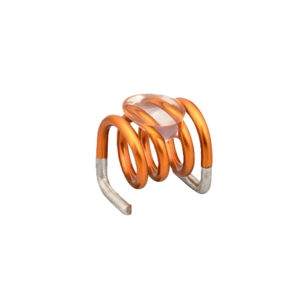
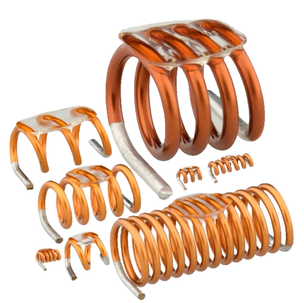
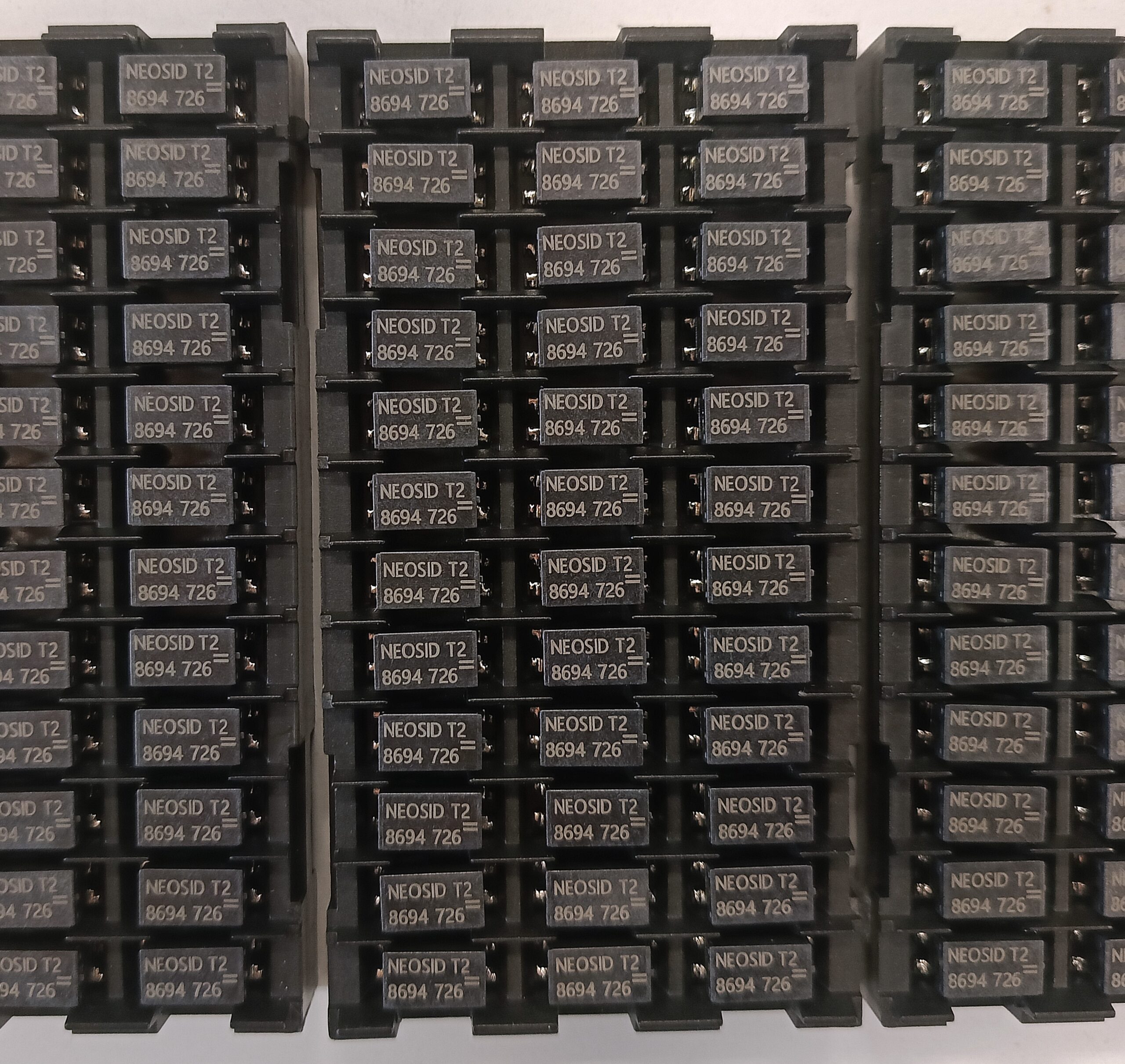
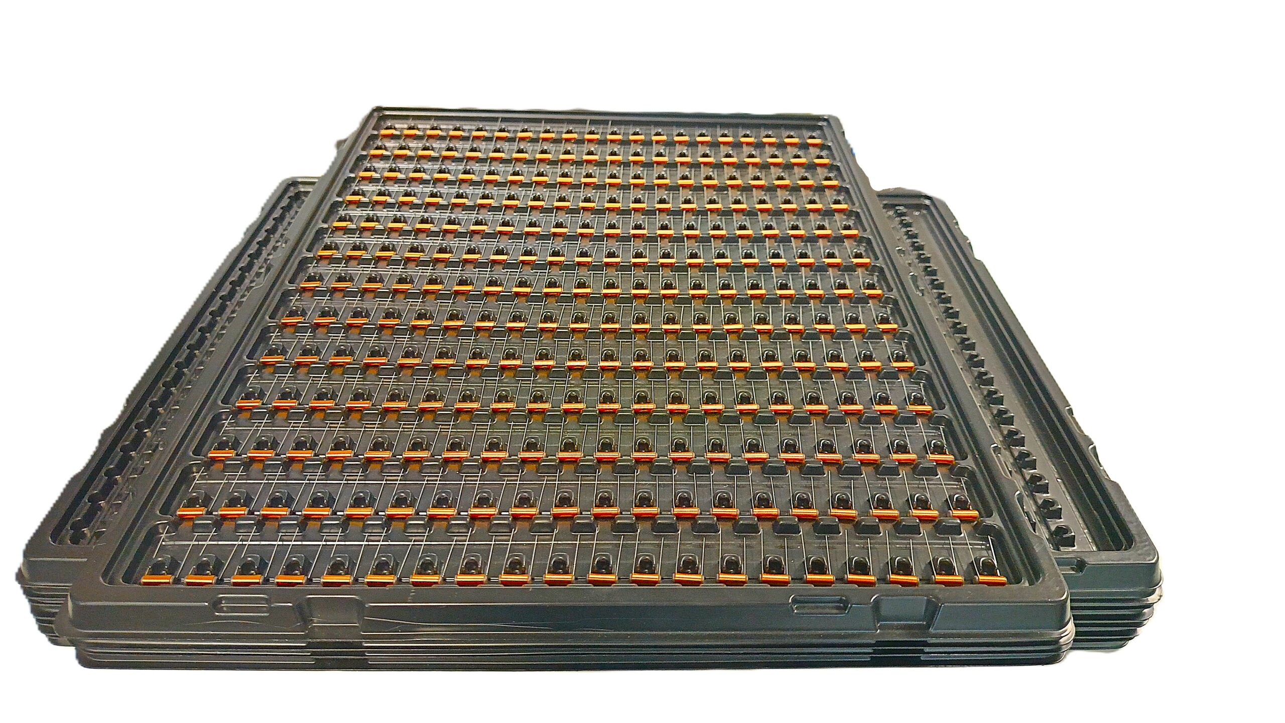
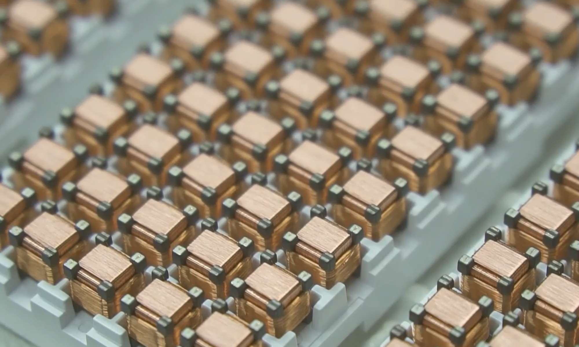
Zdjęcia wyrobów: