Custom SMD inductors – Design and manufacture of dedicated SMD chokes for surface mounting in modern electronics
The miniaturization of electronics, rising operating frequencies, and increasing electromagnetic compatibility requirements are driving a dynamic increase in demand for dedicated SMD inductors. Modern SMD surface-mount chokes are a key component of power supply systems, signal filtering, and electromagnetic interference (EMI) control.
What are SMD inductors?
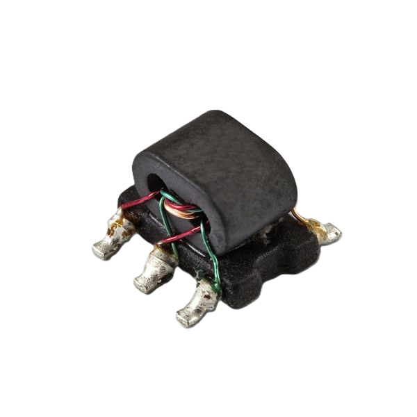
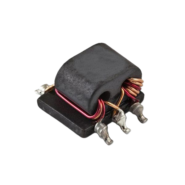
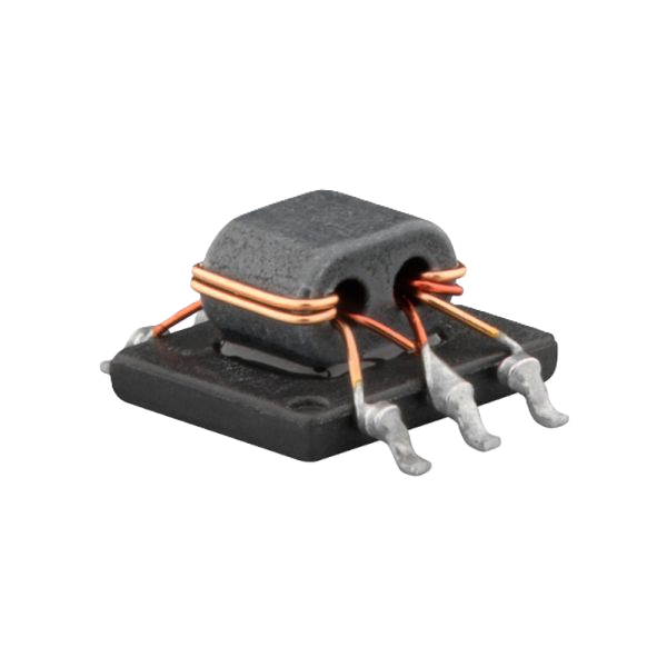
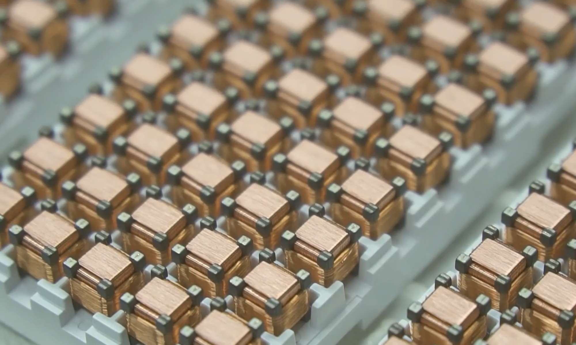
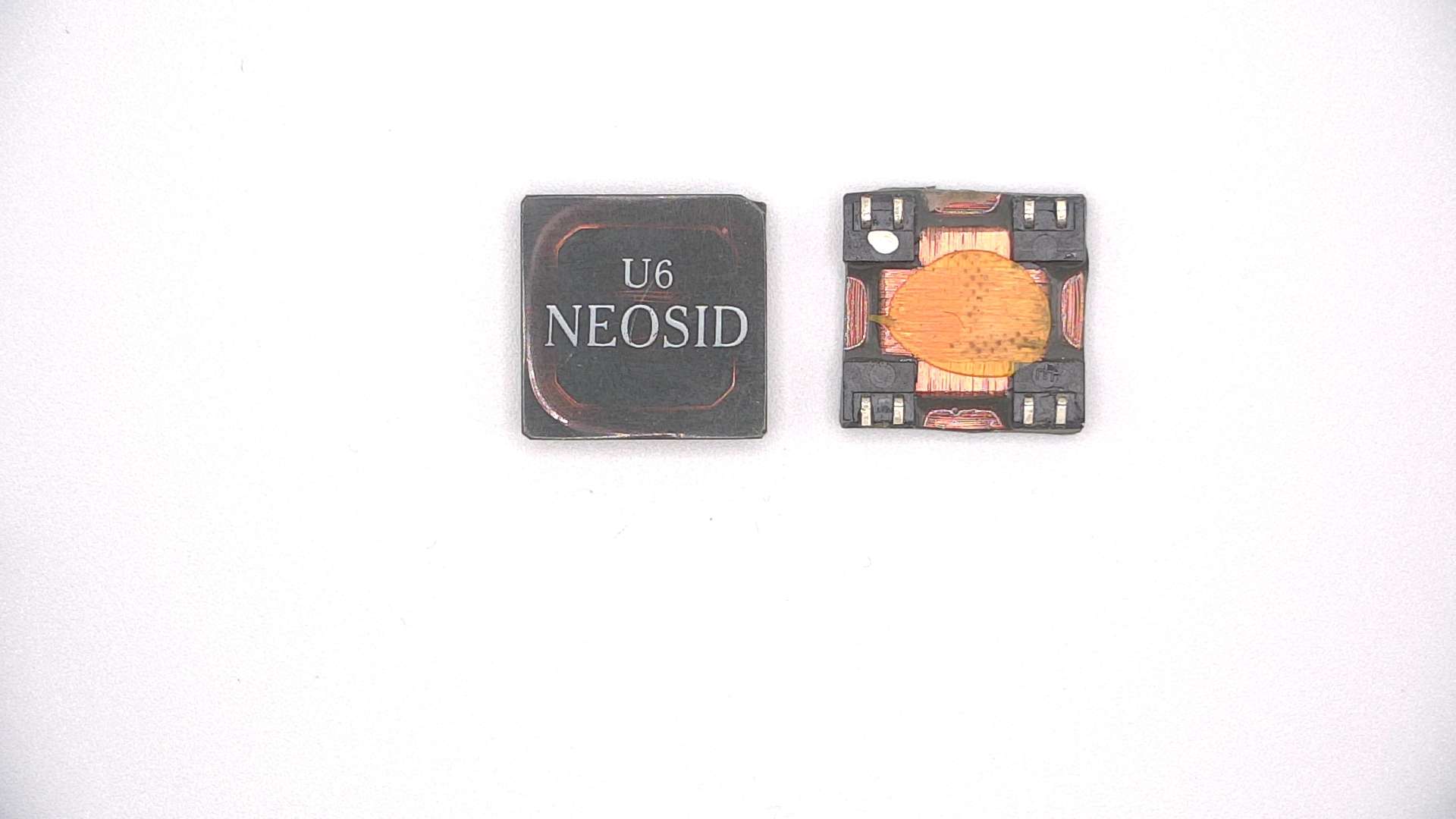
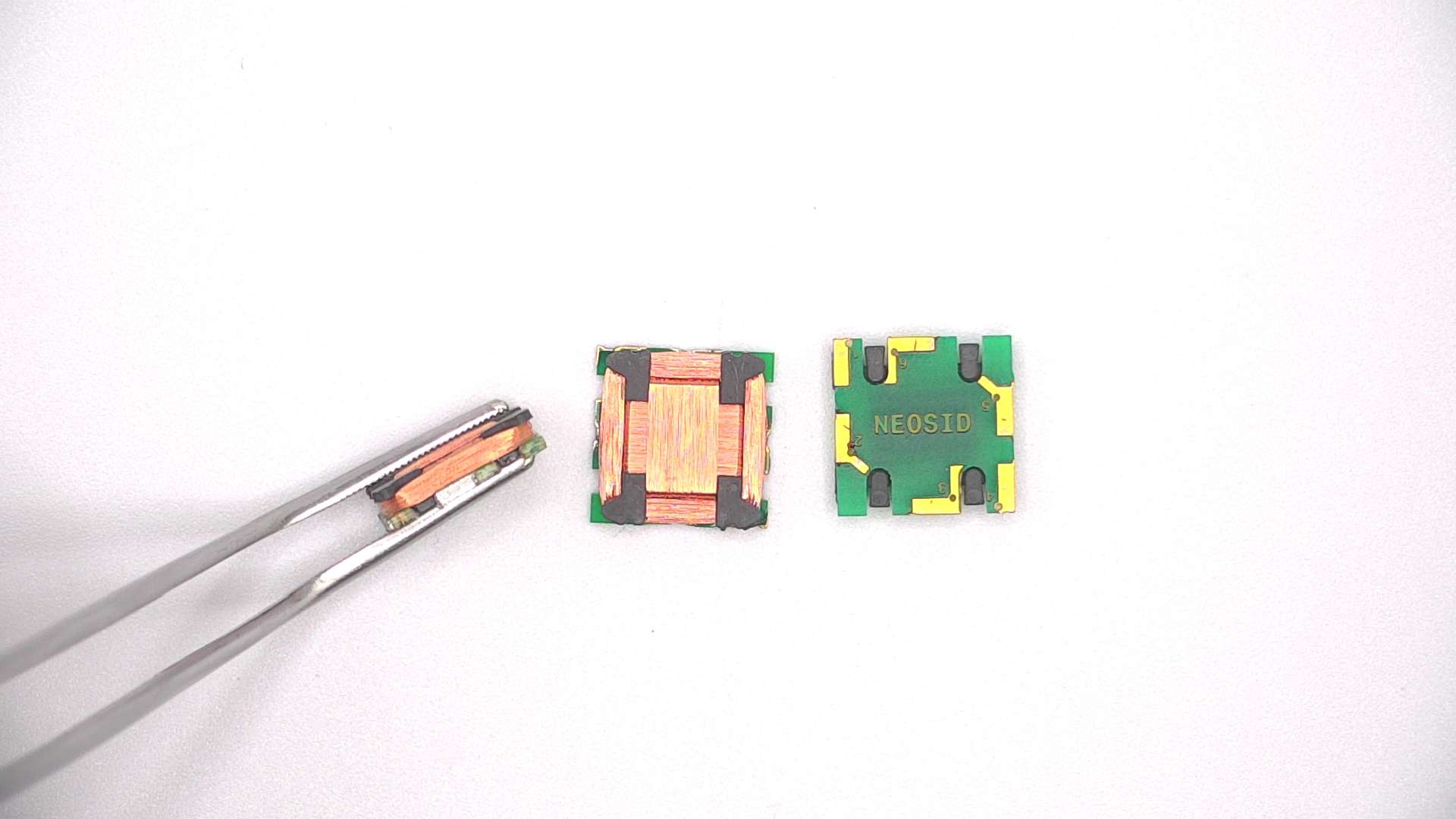
SMD chokes (Surface Mount Devices) are passive inductive components designed for automatic placement on the surface of printed circuit boards (PCBs) using surface mount technology (SMT). Nowadays, SMD chokes can be found in most electronic systems – wherever there’s a PCB and a power supply, there will be SMD chokes: antenna systems, signal filtering systems, transceivers, switching power supplies, automotive electronics, IoT devices, telecommunications, medical equipment, embedded systems, industrial electronics, RF and 5G devices.
Modern SMD chokes are designed to maintain high power density, a low profile, high switching frequency, and minimize losses.

The production of dedicated, custom SMD chokes for surface mount applications typically includes core selection for the target PCB design, winding design, thermal optimization, and electrical parameter measurements. Various SMD choke designs are available, depending on the customer’s specific requirements.
Below are the approximate ranges of electrical and mechanical parameters:
| PARAMETER | SMD CHOKES | |
| Wire type | Solderable and non-solderable: CuL 155 – 200, Gr.1 – 2 (typically) Selfbonding: FSP 18, STP 18, PSP 15 and etc. | |
| CuAg silver-plated wires for HF applications | ||
| Other types of wires are available on request. | ||
| Wire diameter | Min | 0,1 mm |
| Max | 2,10 mm | |
| Other wire diameters are available on request. | ||
| Winding direction | Left, Right | |
| Number of winding layers | Min | 1 |
| Max | TBD | |
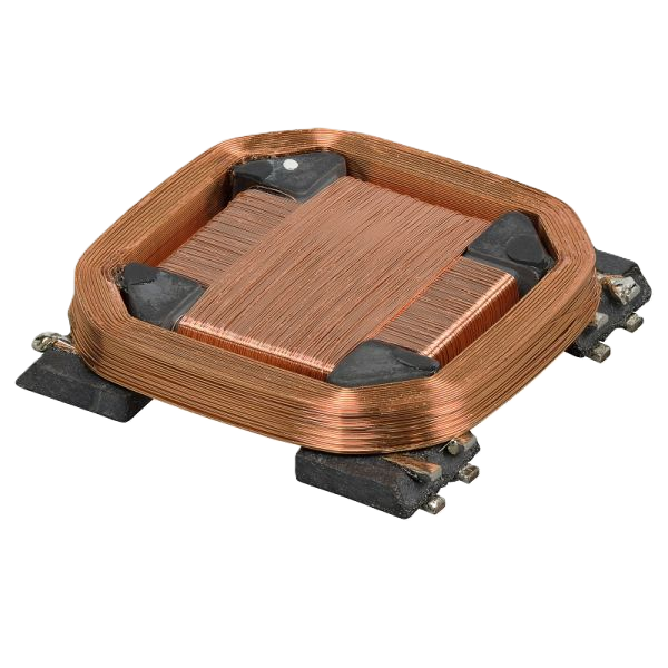
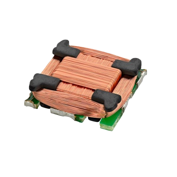
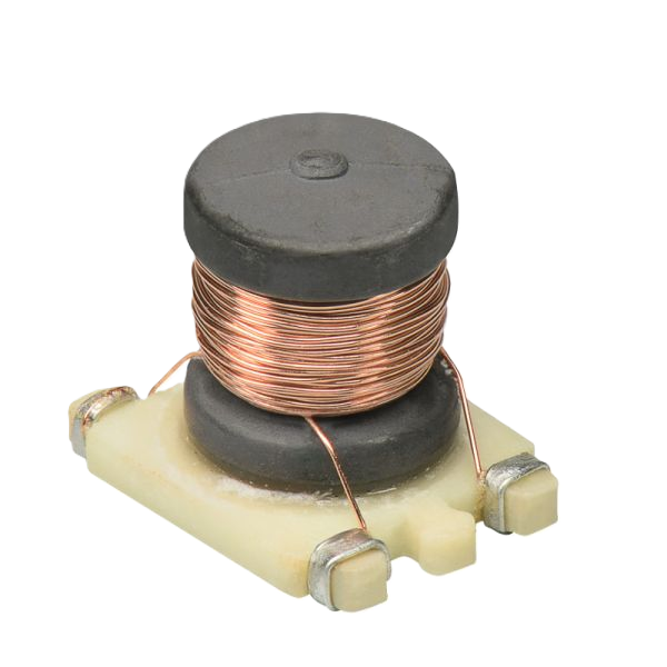
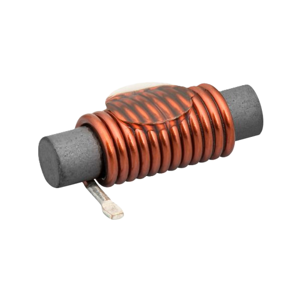
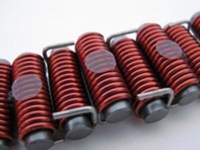
Coil shape | Depends on the shape of the ferrite core. Cylindrical, spool, bar, and others. | |
| Possibility of placing a UV glue point for automatic assembly (Pick & Place machines). | ||
| Unusual, non-typical shapes or requirements – Possibility of individual arrangement upon request. | ||
Types of cores used | Ferrite Cores, Powder Cores, Metal Composite | |
| Typical saturation current ranges (Isat) |
| |
| Typical DC resistance (DCR) |
| |
| Typical operating frequency | Depends on the application and the choice of materials (especially the hysteresis of the ferrite core)
| |
| Leads | Typically – soldered to the core. | |
| Thermocompression welded | ||
| Metalized with silver wire for reinforcement | ||
| Other versions are available upon request | ||
| Location and shape of pins | Typically – wrapping around specific core points | |
| Depending on the core shape – pinout according to the core and customer requirements | ||
Soldering | Pb-Free | |
| Pb (on request) | ||
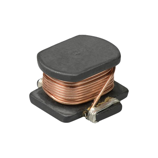
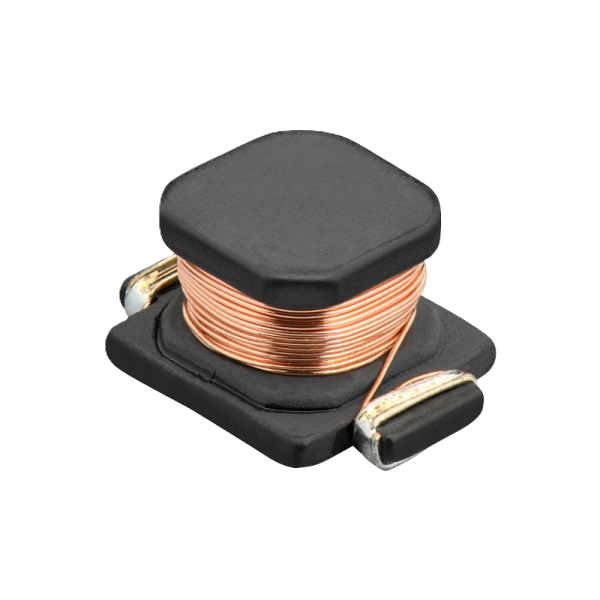
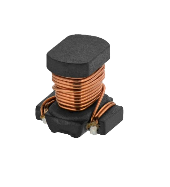
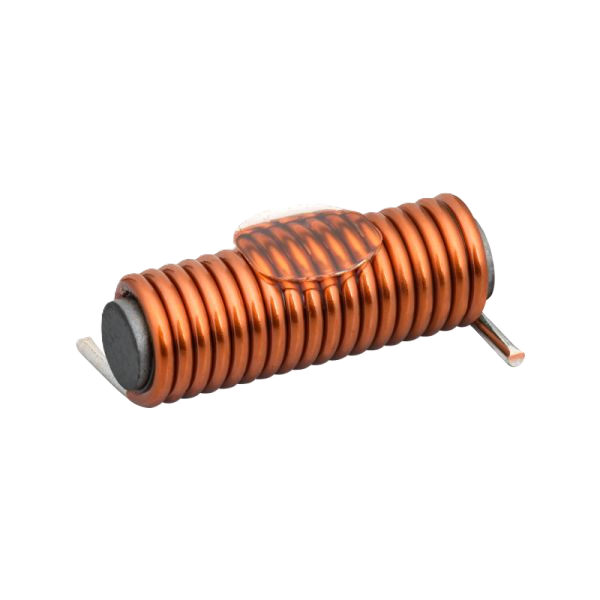
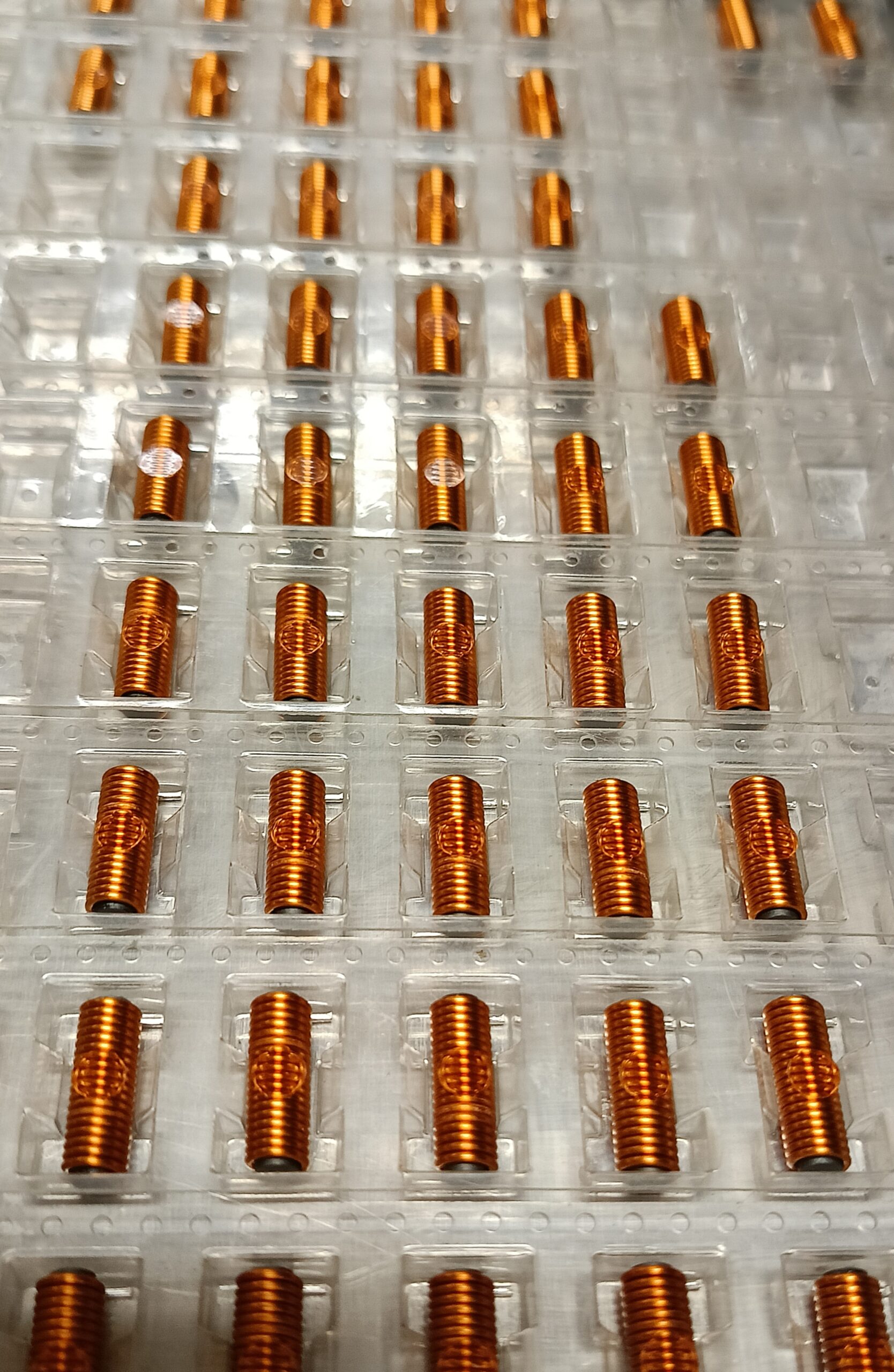
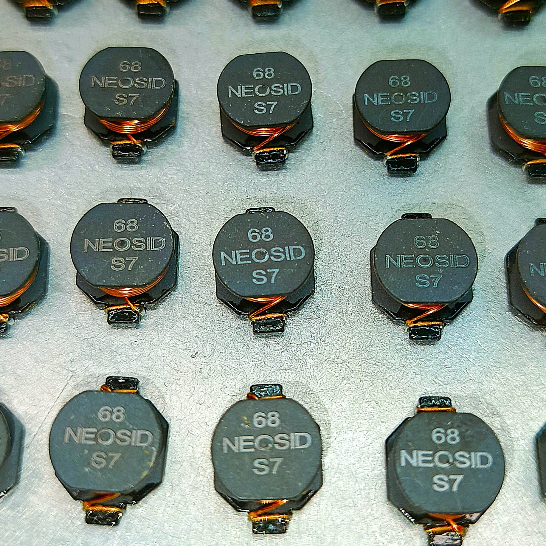
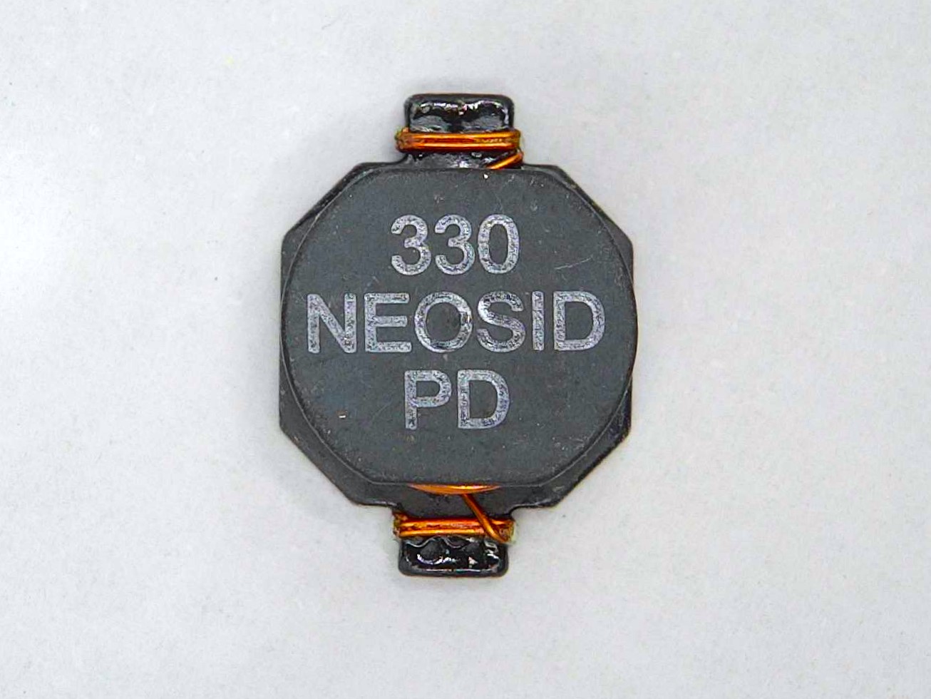
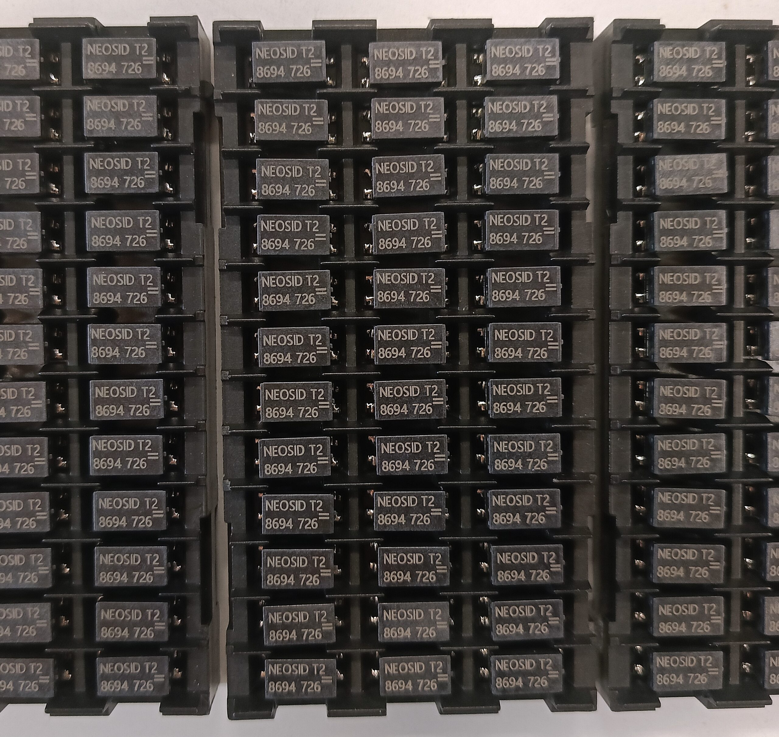
Gallery: