Custom Power Inductors – design and poduction of dedicated chokes to meet the requirements of non-Standard applications
Modern power electronics require components with increasingly higher efficiency, higher power density, and improved EMI performance. Therefore, more and more device manufacturers are opting for custom power inductors designed specifically for specific applications.
Producing custom inductors allows for optimization of:
- DC/DC converter efficiency,
- operating temperature,
- system size,
- EMI level,
- resistance to high pulse currents,
- core saturation characteristics.
Production of dedicated, custom power chokes
Modern power chokes are a fundamental element of buck converters, boost converters, flyback circuits, LLC converters, PFC circuits, SMPS (switched-mode power supplies), industrial inverters, automotive systems, EV chargers, power supply systems in FPGA applications and VRMs for CPU processors.
Power inductors: coils and chokes - Most important technical parameters
The production of dedicated power chokes typically includes design, core selection, winding design, thermal optimization, prototyping, electrical testing, and environmental qualification. Various designs are available: SMD chokes, THT chokes, high-current chokes, common-mode chokes, coupled chokes, planar inductors, and toroidal chokes.
Below are the approximate ranges of electrical and mechanical parameters:
| PARAMETER | POWER INDUCTORS | |
| Wire type | Solderable and non-solderable: CuL 155 – 200, Gr.1 – 2 (typically) Selfbonding: FSP 18, STP 18, PSP 15 and etc. | |
| CuAg silver-plated wires for HF applications | ||
| Other types of wires are available on request. | ||
| Wire diameter | Min | 0.1 mm |
| Max | 2.10 mm | |
| Other wire diameters are available on request. | ||
| Winding direction | Left, Right | |
| Number of winding layers | Min | 1 |
| Max | TBD | |
Coil shape | Depends on the shape of the ferrite core. Cylindrical, spool, bar, and others. | |
| Possibility of placing a UV glue point for automatic assembly (Pick & Place machines). | ||
| Unusual, non-typical shapes or requirements – Possibility of individual arrangement upon request. | ||
Types of Cores Used | Ferrite Cores, Powder Core, Metal Composite | |
| Typical Saturation Current Ranges (Isat) |
| |
| Typical DC Resistance (DCR) |
| |
| Typical Operating Frequency | Depends on the application and on the material selection (especially the ferrite core hysteresis)
| |
| Leads | Typically – soldered to the core. | |
| Compression-welded. | ||
| Metalized with silver wire for reinforcement. | ||
| Other designs are available upon request. | ||
| Lead Location and Shape | Typically – wrapped around specific points on the core. | |
| Depends on the core shape – lead layout according to the core and customer requirements. | ||
Soldering | Pb Free | |
| Pb (on request) | ||
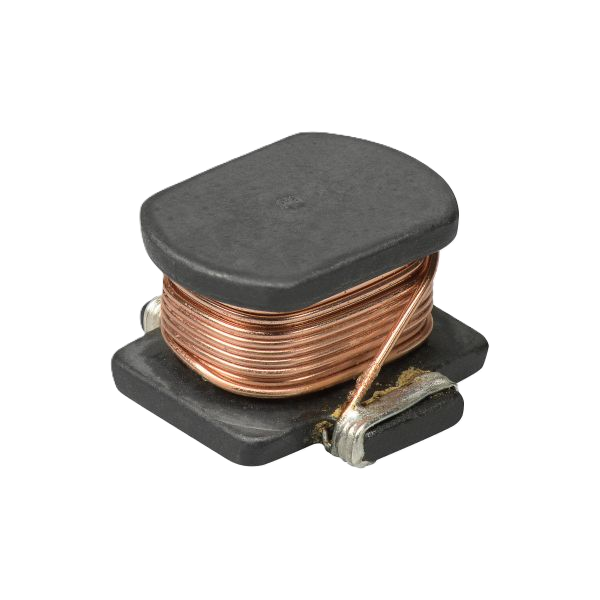
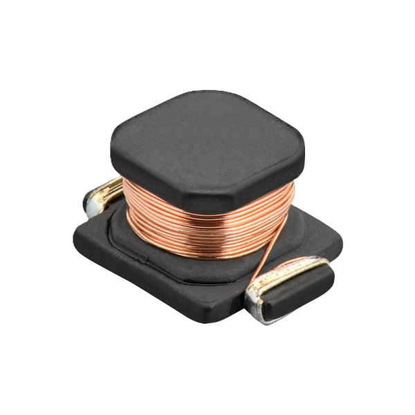
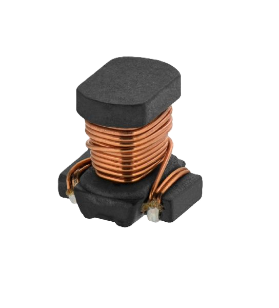
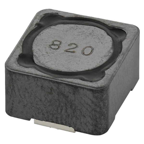
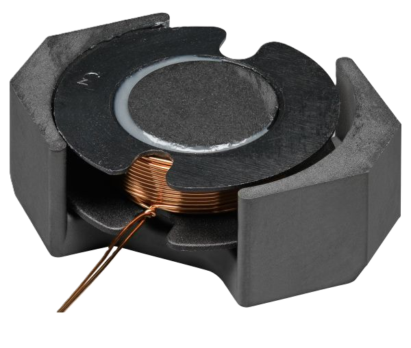
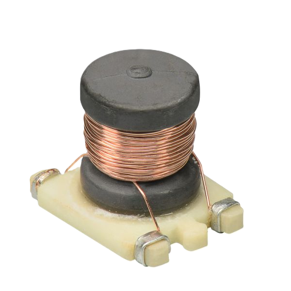
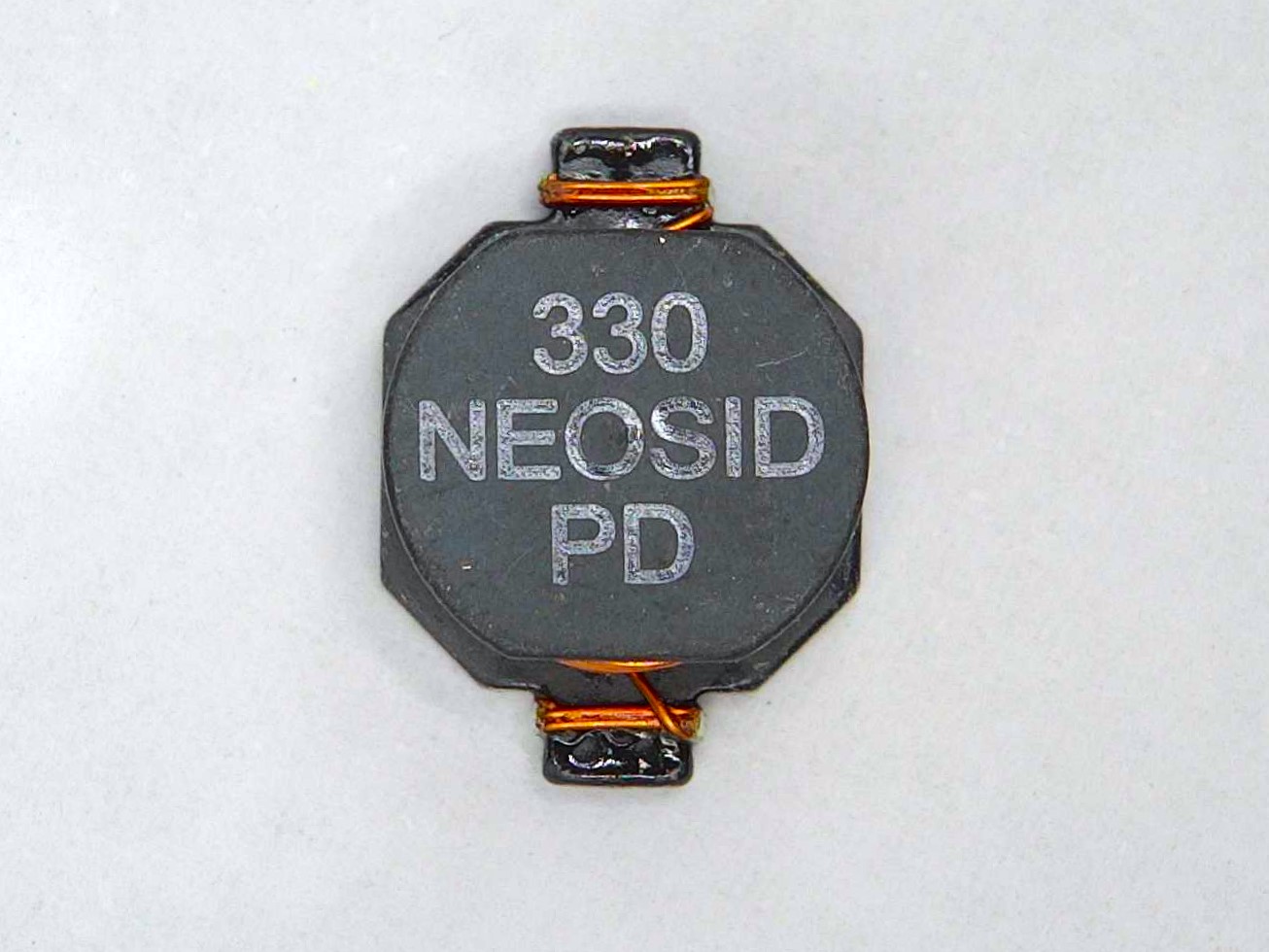
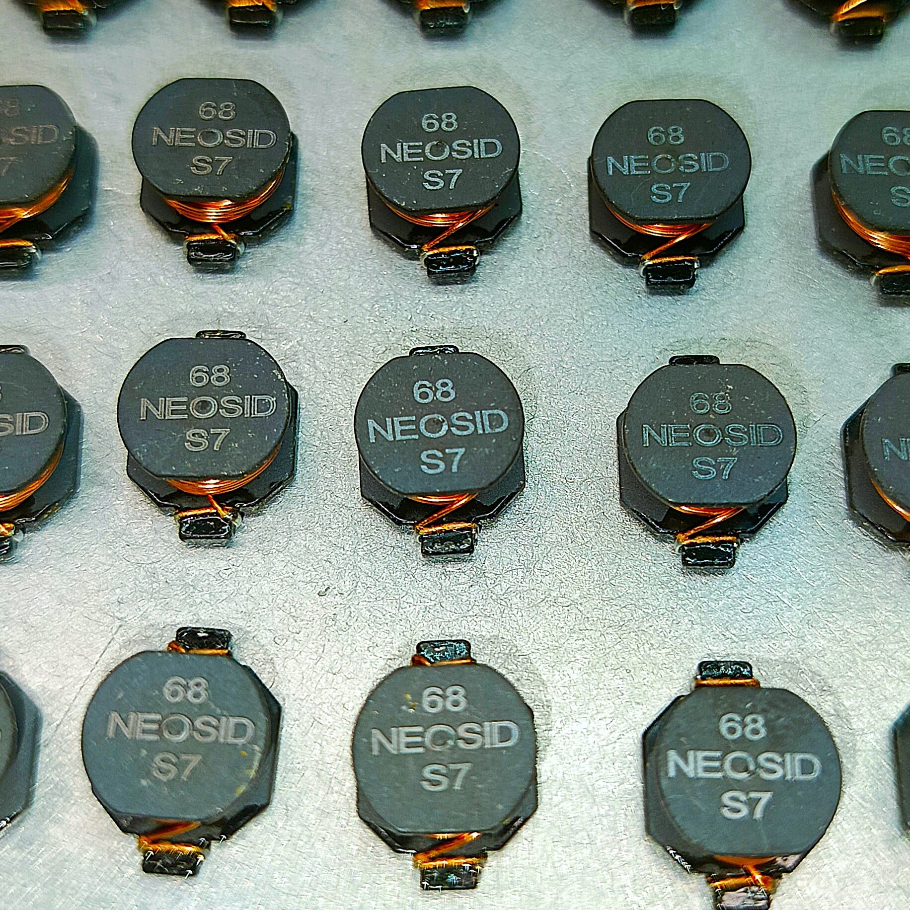
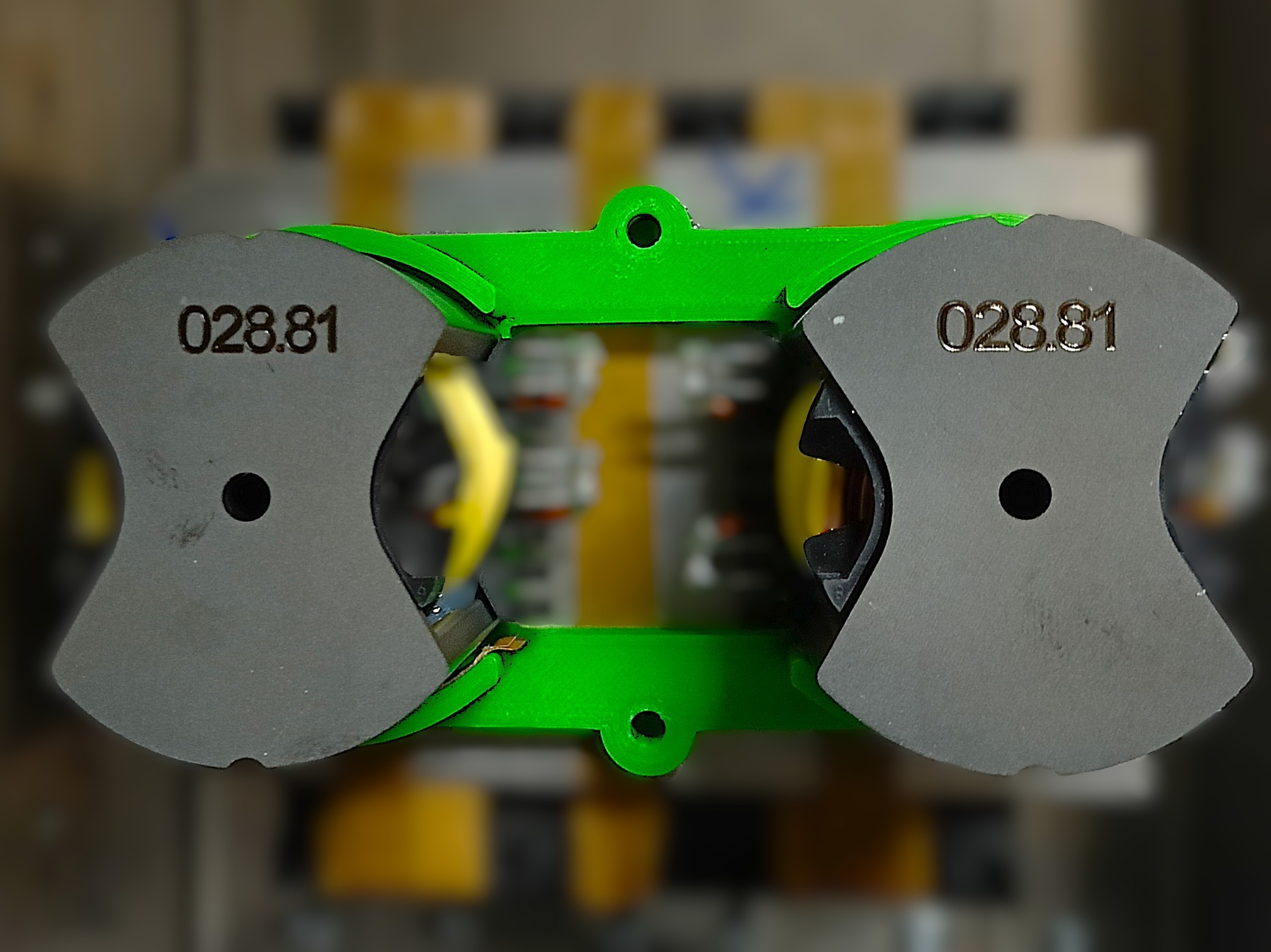
Gallery: